Three-Axis Fingertip
Tactile Sensor
Research on a three-axis tactile sensor for integration into robotic hands.
Three-axis force and contact-position experiments
The video shows contact-position and three-axis force estimates as a probe moves across the sensing surface and applies normal and shear loads.
Sensor structure and sensing principle
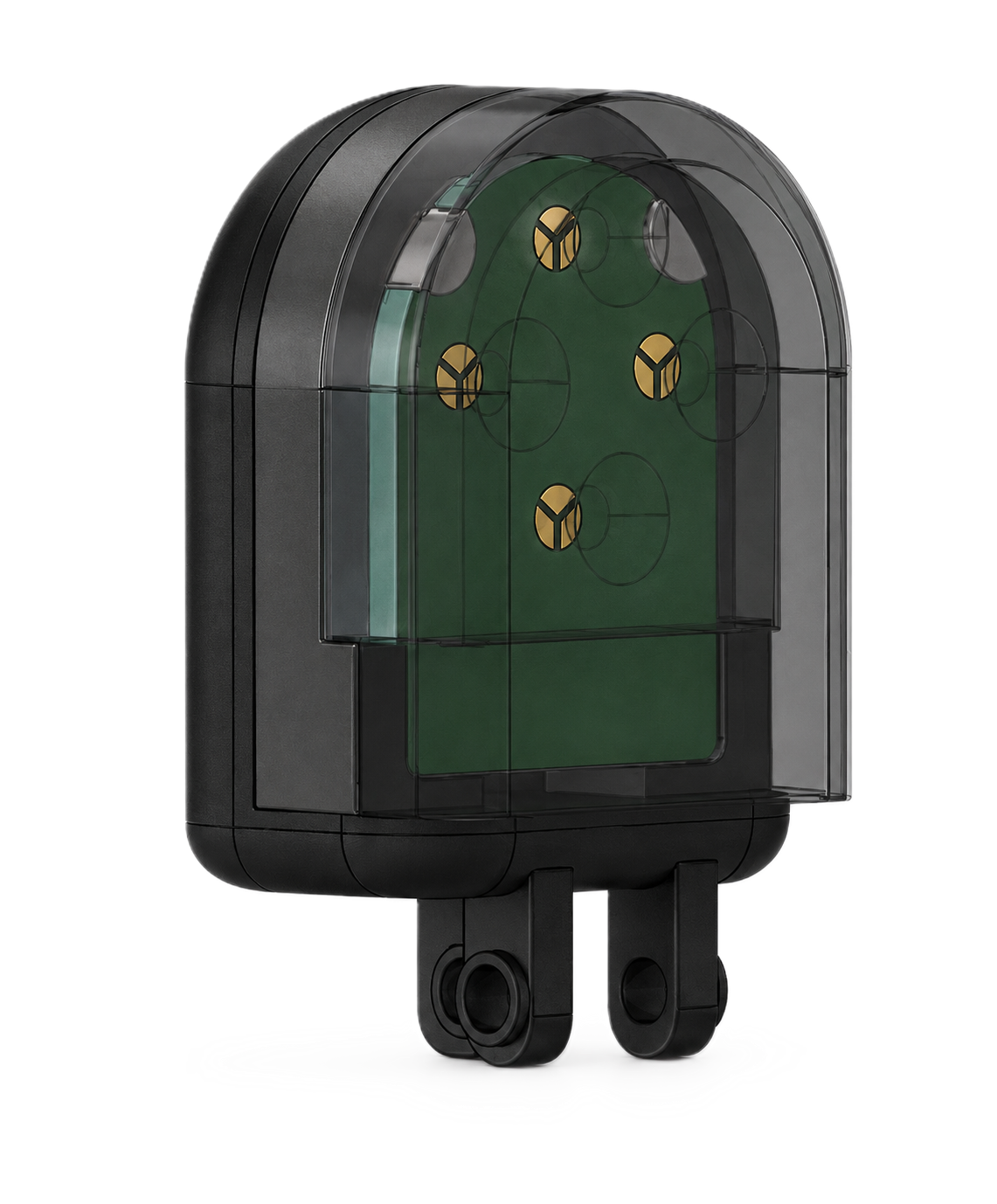
Four inverse-truncated-cone features sit beneath a continuous silicone contact surface. Each corresponding circular electrode is divided into three equal sectors. Normal compression increases the three capacitances together, while shear deformation produces differences between sectors. Common and differential signals are calibrated to estimate the three force components.
Building on the load-transfer structure of the single-axis gripper fingertip sensor by Park et al. (2025), this research introduces three-sector electrodes and three-axis calibration. It also shortens the fingertip assembly for robotic-hand integration and combines sensing, processing and communication circuits in one module.
- Sensor dimensions
- 17.5 × 21.5 × 9 mm
- Electrode configuration
- 4 groups / 12 sectors
- Selected group spacing
- 6 mm
- Electronics
- 4-layer PCB · AD7147
- Contact structure
- Conductive silicone + dielectric
- Outputs
- Fx, Fy, Fz · contact position
Dimensions exclude the finger mounting section. A 6 mm group spacing was selected within the 5–7 mm design range to suit the sensor size.
Electronics and calibration
Three motorized stages and an AFT50-D15 reference force/torque sensor were used. After correcting unloaded offsets and aligning time and coordinate systems, the model was trained with 20 loading repetitions per axis. Evaluation used five separate repetitions per axis.
Normal forces are estimated from the capacitance sum within each group, and shear forces from differences between sectors. Weighted least-squares fitting reduces output on unloaded axes. The four groups’ normal-force contributions are used as weights to estimate contact position.
Force and contact-position estimation
In independent force-tracking tests, RMSE was 0.251 N for normal force and 0.296 N and 0.304 N for the two shear components. The values below are from the calibration selected for force tracking.
| Axis | Recorded evaluation load | RMSE |
|---|---|---|
| Fz | 0–20 N | 0.251 N |
| Fx | Approx. −5.4 to 6.9 N | 0.296 N |
| Fy | Approx. −5.4 to 8.0 N | 0.304 N |
In a separate decoupling evaluation, zero-referenced RMSE between the two shear axes decreased to 0.066 N and 0.109 N. Force-tracking RMSE increased to 0.397 N and 0.391 N, illustrating the trade-off between cross-axis suppression and force tracking.
Contact position was evaluated at 14 locations using a 4 mm diameter probe under approximately 5 N. Three presses were pooled at each location to obtain a median estimate; the mean error of these representative positions was 0.074 mm. This is not an instantaneous error across the full surface or a measure of spatial resolution.
Robotic-hand grasping experiments
Sensors were mounted on an AIDIN-Hand for grasping, holding, release and external-disturbance experiments. Changes in shear force were used to adjust finger closing and increase grasp force.
The reference sensor attached to the object measures the external resultant force, while each fingertip sensor measures a local contact force. Because the load paths differ, differences in magnitude are not treated directly as sensor error.